





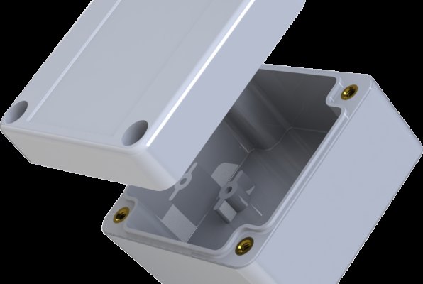
Most moulding defects are decided at the design stage, long before a mould is built. Following a few basic rules keeps parts free of sink marks, voids, warpage and ejection problems, and keeps the mould simpler and cheaper. Our engineers review every new part against these points in the DFM report that comes with our quotation. Values below are general guidelines – the right figure always depends on the material and the function of the part.
Design for a straight pull
A mould that opens in one direction, with nothing blocking the path of the steel, is the simplest and most economical tool. Undercuts – clips, side holes, threads – need slides, lifters or collapsible cores. These are routine for us, but each one adds cost, maintenance and cycle time, so it is worth asking whether a feature can be redesigned to release in the opening direction.
Keep wall thickness uniform
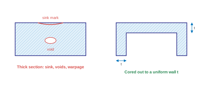
Plastic shrinks as it cools, and thick sections cool last. They pull inward and leave sink marks on the surface, voids inside and internal stress that turns into warpage. Design a nominal wall – typically 1.5–3 mm for most engineering resins – and core out thick areas instead of filling them with material. Where the wall must change, make the transition gradual, over a length of about three times the difference.
Add draft to every wall
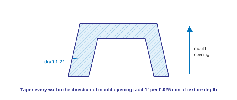
Draft is the taper that lets the part release from the mould. Without it parts stick, scuff or distort on ejection. Use at least 0.5° on smooth surfaces and 1–2° as a normal value. Textured surfaces need more – as a rule of thumb an extra 1° for every 0.025 mm of texture depth.
Holes
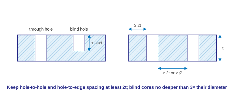
Holes are formed by core pins, and plastic flowing around a pin leaves a weld line. Holes in the opening direction are simple; holes at an angle need side actions. Keep the space between holes, and between a hole and an edge, at least twice the wall thickness. A blind-hole core is supported at one end only, so keep its depth to about three times its diameter.
Bosses
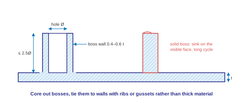
Bosses locate parts and take screws or inserts. A solid boss creates a thick section and a sink mark on the visible face. Core the boss, keep its wall at roughly 40–60% of the nominal wall, limit its height to about 2.5 times the hole diameter and connect it to nearby walls with ribs or gussets.
Ribs
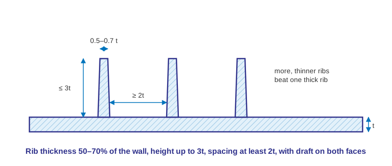
Ribs add stiffness without adding wall thickness. Make them 50–70% of the nominal wall thick (towards the lower end for cosmetic surfaces), no taller than about three times the wall, at least two wall thicknesses apart and with draft on both faces. Several thin ribs are better than one thick one.
Round the corners
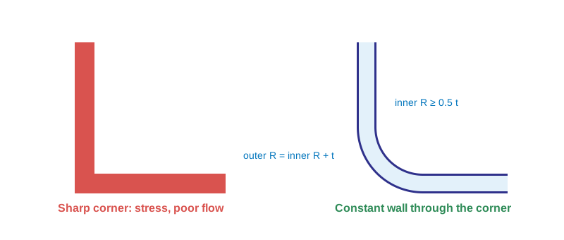
Sharp corners concentrate stress, disturb flow and are a common starting point for cracks. Use an inside radius of at least half the wall thickness, and an outside radius equal to the inside radius plus the wall thickness so the wall stays constant through the corner. Add small radii at the base of ribs and bosses as well.
Material and processing
Geometry is only one third of a good part. Material selection – shrinkage, stiffness, heat and chemical resistance, appearance – and processing conditions have equal weight. We mould commodity and engineering resins including PP, ABS, PC, PC/ABS, PA, PMMA, POM and PS, and can recommend grades for your application. Read more about our mould design and DFM service.
Have a part to discuss? Send your drawing or 3D file to info@chinaunitedmould.com or use our inquiry form – our engineers reply with a quotation and DFM suggestions.