Electronic control board cover: single-cavity ABS mould, 1,000 parts
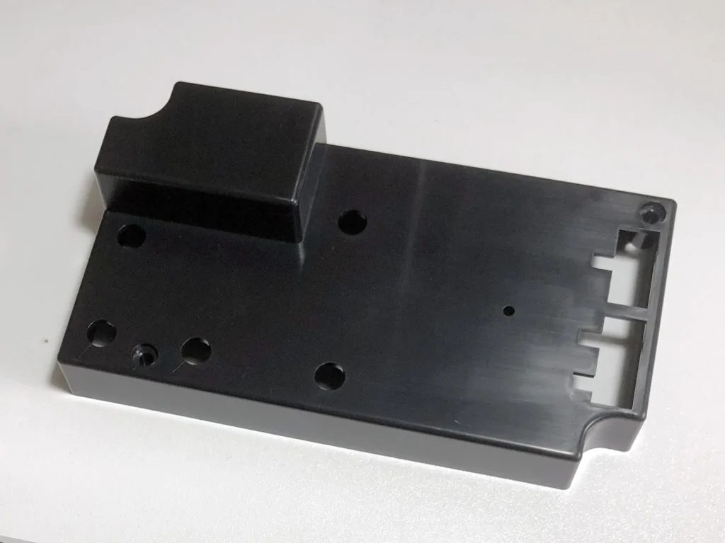
A customer in Italy sent us the 3D file of a cover for their new electronic control board. We reviewed the design, built a single-cavity mould, fixed a sink mark after the first shots and produced the first 1,000 parts.
General polish (labels are applied to the surface)
First order
1 mould + 1,000 parts
Timeline
From deposit to 1,000 parts in 93 days
Day 0Deposit
Order for 1 mould + 1,000 parts
Day 3DFM report
Gate, ejection and draft checked
Day 10Mould design
Approved by the customer
Customer approval
Day 57T1 samples
Ready after one design change
Day 86Approved
Cover tested on the control board
Customer approval
Day 931,000 parts
Moulded and packed, 11 cartons
Step 1
The request
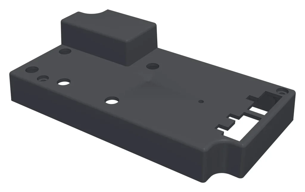
The customer sent a STEP file of the cover for their new control board and asked for a mould price plus part prices for 500, 1,000 and 5,000 pieces in black ABS. We sent the quotation the next day. Three months later, once their own electronics prototype was ready, they ordered one mould and the first 1,000 parts.
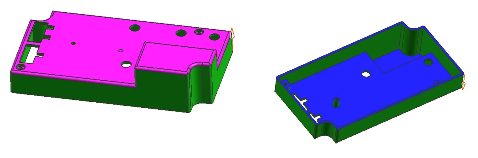
The customer's 3D model of the cover
Step 2
Surface finish and DFM
Before cutting steel we sent photos of three finishes – general polish, texture and mirror polish. The customer chose general polish because labels are applied to the cover.
Three days after the deposit we sent the DFM report:
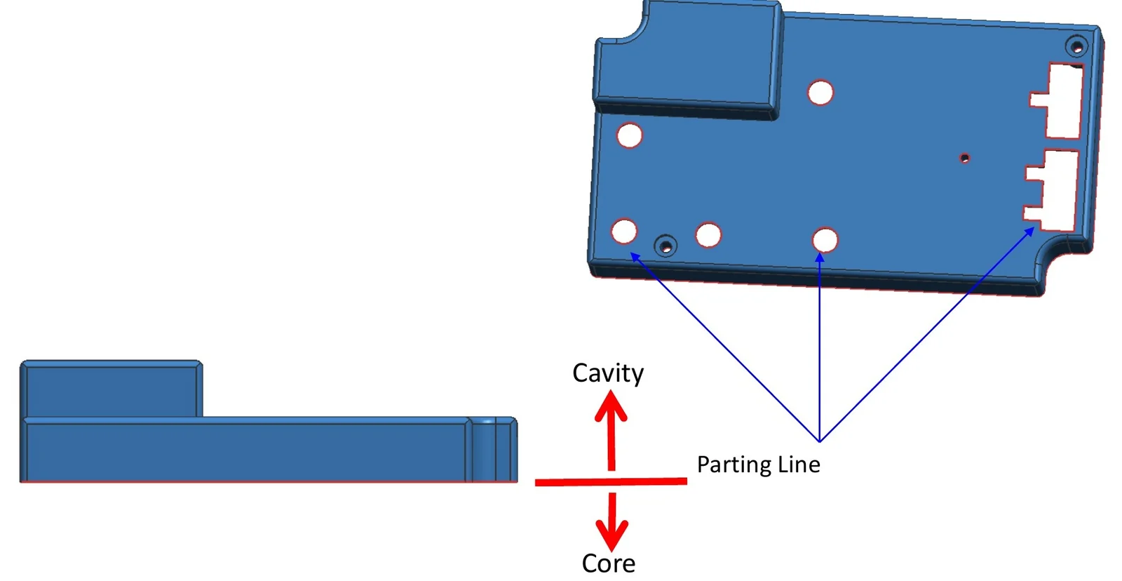
Parting line – kept off the main visible surface.
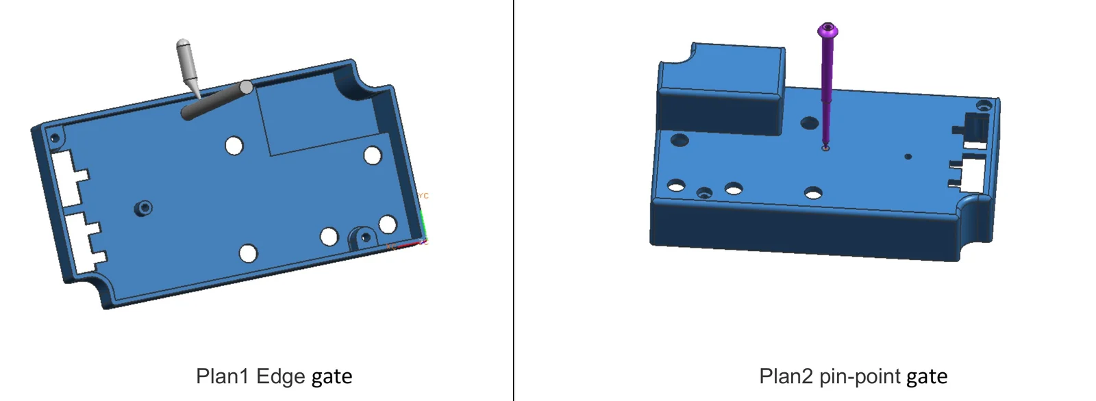
Gate – two options, an edge gate or a pin-point gate. The customer chose the edge gate.
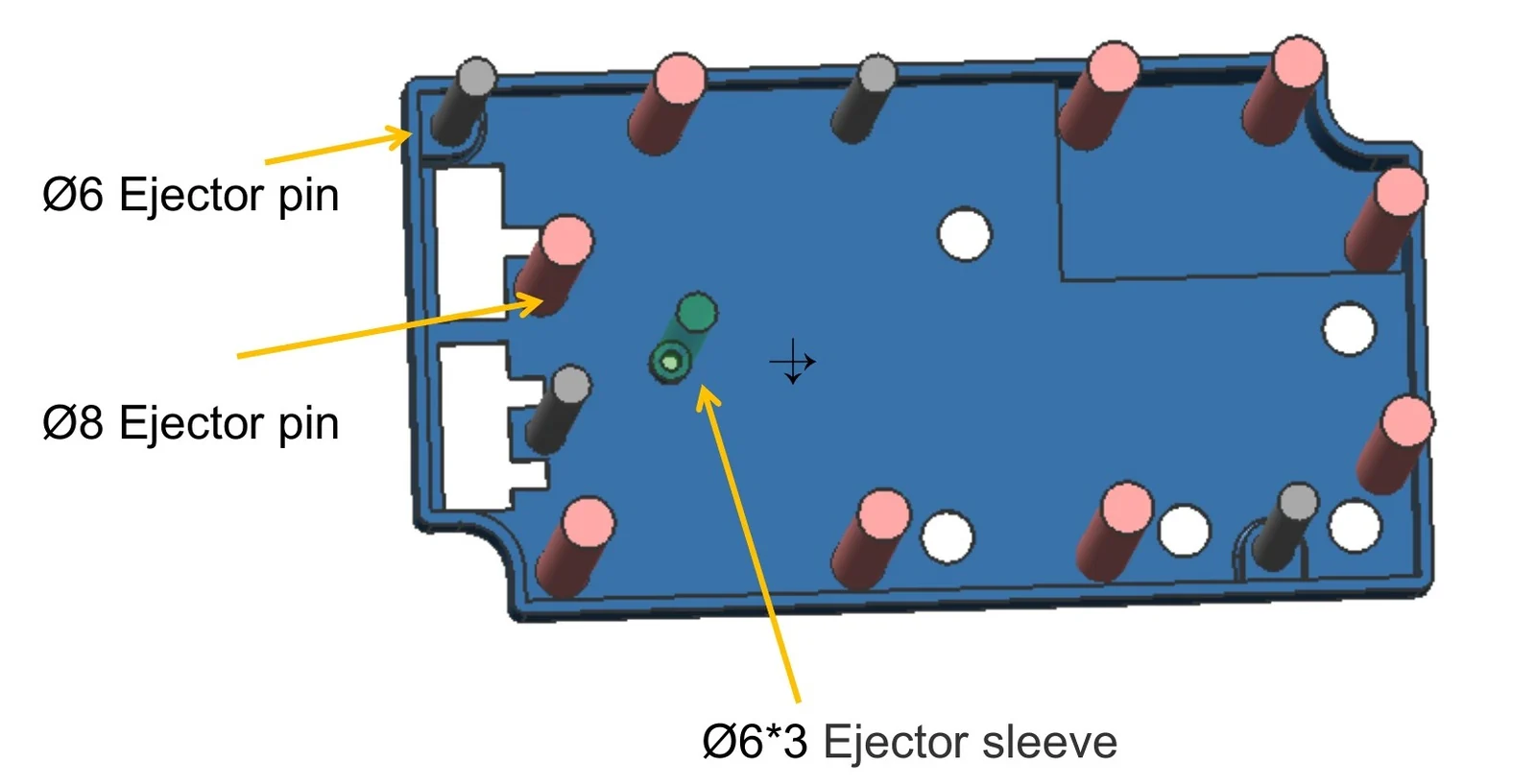
Ejection – Ø6 and Ø8 ejector pins plus a Ø6 ejector sleeve, placed away from the cosmetic face.
Draft – 2° draft added to the faces that would otherwise stick in the mould; a revised 3D file was sent for confirmation.
The customer’s technical department checked the report and sent back an updated STEP file.
Parting lineKept off the main surface.
Gate optionsEdge gate vs pin-point gate – the customer chose the edge gate.
EjectionEjector pins and sleeve placed away from the cosmetic face.
Draft2° draft added to the faces shown in green.
Step 3
Mould design review
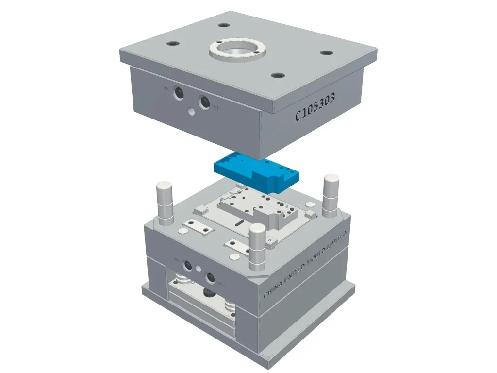
The customer asked to see the mould design before we started, so we sent the full 3D mould design. They approved it the next day and toolmaking started.
Mould design, opened at the parting line to show the core
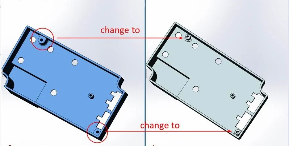
Sink-mark fix: bosses shortened and radiused (left: original, right: change)
Step 4
First shots and a design fix
The first shots showed sink marks where thick bosses joined the outer wall. We sent the customer photos and a proposed change. The same day they sent a revised 3D file: the two bosses were shortened and given a 1 mm radius at the base. We modified the mould to match.
Step 5
T1 approval and shipment
T1 samples went to Italy by express courier. The customer’s technical team fitted the cover onto the control board, tested all connections and approved it for production.
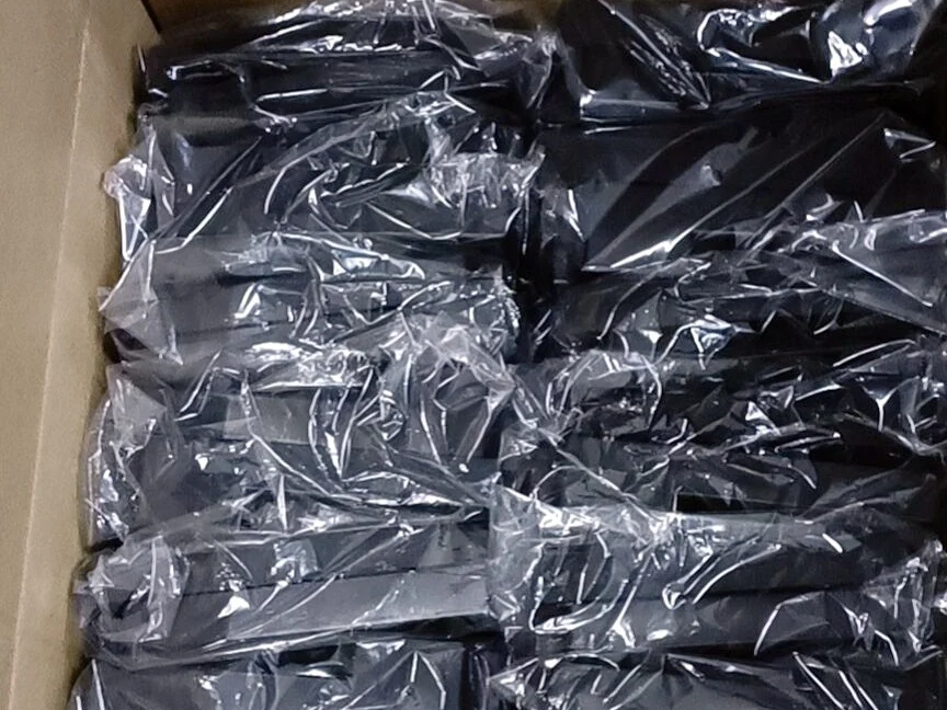
The first 1,000 parts were moulded and packed within a week of approval: 11 cartons, 55.8 kg gross. Collection from our factory was arranged with the customer’s own courier.
1,000 parts bagged and packed for shipment
Have a project in mind? Send us your drawing for a quotation.